Flow Control Valve: Definition, Types, Components & Working Principle
What is Flow Control Valve?
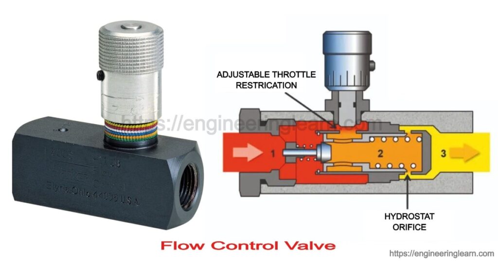
Flow Control Valve: Definition, Types, Components & Working Principle :- Flow regulating valves are also known as speed control valve. The primary function of the flow control valve is flow control in a pneumatic system and regulates the pressure of flow of fluid. Flow control valves in hydraulics are used for controlling the volume of fluid which is supplied to different parts of the hydraulic system.
The speed of the actuators which is being used in the hydraulic circuits can be controlled by regulating the fluid flow, to carry out this regulation operation we need devices and the device which is providing that regulation operation is flow regulation valves.
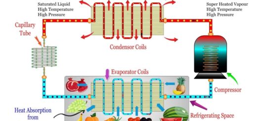
Compensation of Temperature Change in Flow Regulating Valves
In addition to the pressure compensation the hydraulic systems are having the temperature problem as well, lot of moving components are there and the friction of the moving components is generating the heat energy. As the temperature is increasing that is affecting the viscosity of the hydraulic fluid, the viscosity will be reduced. As the fluid viscosity is reduced, flow rate is changed. By reducing the area of valve opening, the fluid flow can be reduced and by increasing the area of the valve opening fluid flow can be increased.
Flow Regulating Valve Example in Daily Life ( Tap)
Household tap is a very common example of flow regulating valve. Flow regulating valve in household tap contain flow adjustment screw having a ball. By rotating the flow adjustment screw, orifice area can be varied. If the area is reduced then the flow would be restricted or minimized. As the area of orifice is increased by rotating the flow adjustment screw more amount of fluid will pass through the passage.
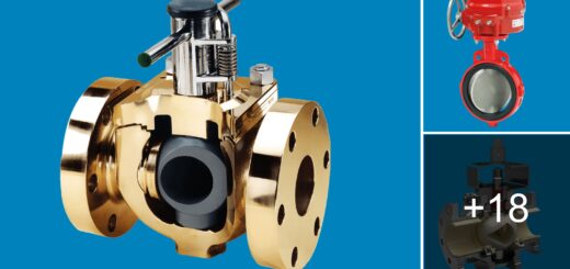
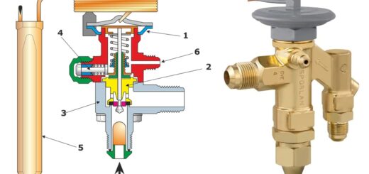
Components of Flow Control Valve
1. Valve Body
It is also known as shell. It is used as primary pressure boundary of valve. Everything is being hold together by the framework called valve body. The inlet and the outlet piping is received into it with the help of bolted, welded joints. It is cast into various shapes in which the cylindrical and the spherical is the economical one.
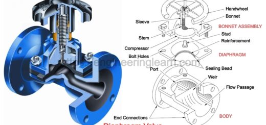
2. Valve Bonnet
It is the cover provided for the opening in the body of valve. The body is split in two parts which is bolted together. Some valve bonnets used as a valve covers only while some of them are used for support valve internal accessories like actuator, stem and disk.
3. Valve Trim
It is referred to the elements which is present in internal of a valve. It consists of stem, sleeves, seat and disk. The performance of the valve can be ascertain by seat and disk interface.
4. Disk and Seat
Disk is a element which allow and restrict the fluid flow. When disk is at closed state then total system pressure is exerted on the disk and the outlet side is depressurized. Seating surface for a disk is provided by the seat.
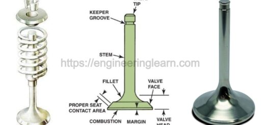
5. Stem
It is that element which is responsible for the connection of actuator and the disk and keeps the disk in its position. The connection of stem with the disk is done with the help of threaded or welded joints. There are two types of stem non- rising stem and rising stem. In rising stem when valve is open then the stem will rise above actuator. And in case of non rising stem there is not any upward movement of stem.
6. Valve Actuator
It is the element by which stem and disk assembly is being operated. It can be operated manually or by electric motor.
7. Valve Packing
This element is used for packing in valves which in result prevents the leakage between stem and bonnet.