Punch Press Machine Component and Types
What is punch press machine?
Punch press machine is defined as the type of machine press which is used for cutting holes in material. It can be manually operated, small in size and can hold one simple die set or it can be very large which can be CNC (computer numerical control) operated which can hold large and complex die set and have a multi station turret.
Punch presses machines are large machine with either a bridge or portal type frame or a C type frame. At the top foremost part of the C type has a hydraulic ram but the portal frame is much similar to complete circle in which ram being centered inside the frame for stopping the frame from distortion or deflection.
Characteristics of punch press machine:
The Punch press system is characterized by parameters like:
- Type of frame
- Mechanism by which the power is delivered to ram (hydraulic, mechanical or electro–mechanical)
- Working area size
- Multiple or single station
- Force rating
- Tool shop capacity and its type
- Productivity or speed (generally specified by strokes speed with step movement)
- Without shock speed of movement (speed – load displacement)
- Work piece maximum weight
- Consumption of power
- Software type
- Safety features
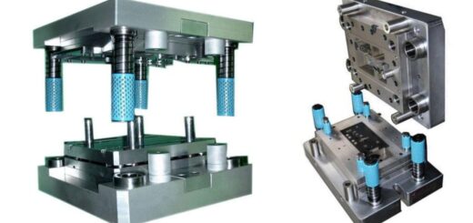
Components of Punch press machines are:
- Bed or base: The bed and base is one of the significant components of the system and are the lower most part of frame and give support to work piece holding dies and various control mechanism of the system. Size of work piece which is being operated is based on the size of base.
- Frame: Frame is used to support the structure of the punch press machine. It also supports the controlling mechanism and ram driving mechanism. Frame are divided into two parts, the lower part known as bed while the upper part known as crown.
- Ram: Ram is the most important part used in operating the punch press because it directly works on work piece. It moves up and down between the guide-ways where the stroke length and strength are predetermined. The up and down motion of the ram is called stroke. Power mechanism or motor are there in crown for supporting up and down movement of ram.
- Pitman: It is that part of punch press machine which connects ram and crankshaft.
- Driving mechanism: Driving mechanism uses eccentric mechanism and crankshaft for driving the ram by supplying power from motor to ram.
- Controlling mechanism: Under calculated control condition controlling mechanism are used for the operation of Punch press machine. Two mechanisms are adjusted by the controlling mechanism which is power of the ram stroke and length of the ram stroke. They give accurate and reliable control with automation. Nowadays microprocessor is used for guiding this operation of the machines.
- Flywheel: It is energy storing device of punch press. Flywheel is used to maintain constant speed of ram and for avoiding the fluctuations.
- Brakes: It is one of the crucial part of the punch press system because they help to prevent accidents. Normally punch press machine have two brakes, one emergency brake which have normally stronger braking having power shut switch and another is a standard brake which bring the driveshaft to rest by disconnecting it from flywheel.
- Bolster plate: Bolster plate is thick plate which is attached to the punch press base for clamping the bottom part of die.
Punch press systems are generally referred by their table size and tonnage. The Punch press system nowadays mostly uses 30 – ton press. The tonnage is used for form and cut the material.
Principle of working of punch press:
The punch press machine works on conversion mechanism principle which converts the rotary motion into linear motion. The power is provided by the motor to drive the flywheel. With the help of connecting rods and clutch, flywheel drive crankshaft. A transfer point is needed in between the connecting rods and the slider for converting the circular motion into linear motion. Drive mechanism powers the ram up and down motion during operation. The metal strip passes in between die shoes during the operation and the punch moves down exerting pressure on metal sheet. This makes a hole through the sheet and then through the opening of the die, the detached portion falls off.
Operation of punch press machine:
A Punch press system has two major components:
- A punch: It is attached to a reciprocating ram of machine.
- A die: It is clamped onto anvil or bed and the flat surface of anvil or bed is perpendicular to the ram path. Die set contain a set of dies and punches which is pressed together to deform or to make a hole in the work piece according to the desired manned. The dies and the punches are removable where punch is attached to ram in the process of punching. The ram in vertical linear motion moves up and down and force the punch into die through the material.
For operation the punch press system is being pushed against the work piece which is held in die and the slug of metal sheet is shear out with the help of blanking die for making it blank so that it can fit dies for consecutive punch – press operations. Generally the punch press system is driven with the help of electric motors and conversion from drive shaft’s rotary motion for reciprocating the ram which is affected by either toggle, cam mechanism or a crank. A flywheel is attached to drive shaft due to its intermittent power demands for storing the energy at period between ram strokes and for delivering energy to shaft at the period of punching operation which leads to the reduction of capacity required by the driving motor.
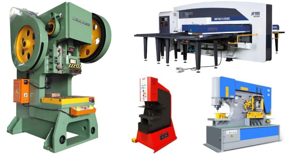
Types of Punch press machines:
Punch press machines are differentiate on two basis
1. According to drivers type Punch press machines are of four types:
A) Flywheel drive Punch pres:
Generally most of the punch presses present today are hydraulically powered while the punch presses present in older days had mechanically driven rams which means power was provided to the ram from heavy, constantly rotating flywheel. Flywheel drive the ram with the help of a Pitman arm but during 19th century they are powered with the help of leather drive belts which are attached to line shifting which helps in running a steam plant. Nowadays flywheel drives are powered with the help of electric motor.
B) Mechanical Punch press:
Mechanical Punch press is of two different types which are based on type of braking or clutch system which is equipped in it. Older presses are normally full revolution presses which need full revolution of crankshaft for punch press to come to stop position but this full revolution clutch presses are dangerous and are outlawed in very countries till the point of pinch are fully guarded because braking mechanism of the punch press depends on set of raised key to be fall in the matching slot for stopping the ram. Ram can be stopped at the same location which is the top dead centre by a full revolution punch press.
The punch presses which are newly developed are generally part revolution presses which are equipped with braking system which is similar to the brakes used on commercial trucks. Band – type brake expands and permits the crankshaft to revolve when the air is applied. The air is bled when stopping mechanism is applied which results in the braking system to close and clutch to open, and stop the ram in any part of rotation. Revolution clutch and brake are generally combined unit which is used to operate in fail safe mode, clutch is engaged by a dual air safety valve thus start slide motion and then the brake is applied by springs.
C) Hydraulic Punch press:
With a hydraulic cylinder instead of flywheel hydraulic punch press power the ram and are either valve and feedback controlled or valve controlled. Generally valve controlled machines permit one stroke operation which allow the ram to stroke down and up according to the command whereas the feedback controlled system permit the ram to controlled proportionally within fixed points according to the command which provide great control over the ram’s stroke and leads to increasing the rates of punching because the requirement of full stroke up and down of ram has ended but hydraulic punch press operation can be done within very short window of stroke.
D) Servo drive turret punch press:
Twin AC servo drives are used by servo drive turret punch press which is directly coupled with drive shaft. And drive system add the simplicity of original brake and clutch system with the hydraulic ram driven system speed which results in reliability, low operating costs and high performance. A servo drive press system has no oil – cooling chillers or complex hydraulics which reduce the repair and maintenance costs. It can be equipped with modern and advance technology which can reuse and stores energy which is generated at the time of ram deceleration which provide electrical power savings.
2. According to Slider Movement Punch Press machines are of three types
Single action, double action, three action presses but generally single movement punch press is commonly used while the double action and three action presses are normally used for the production of large – scaled parts like car body.
Advantages:
- High volume production.
- Consistent quality and good repeatability.
- High speed processing and labor requirement is less.
- High accuracy.
- Operation is simple.
Disadvantages
- High initial cost.
- High volume quantities is required for being economical therefore short – term productivity is costly and inefficient.
- For small parts they are too heavy.
- They produce noise.
- It may require skilled person if complex parts are involved.