Wankel Engine (Rotary Wankel Engine) Applications
What Is Wankel Engine?
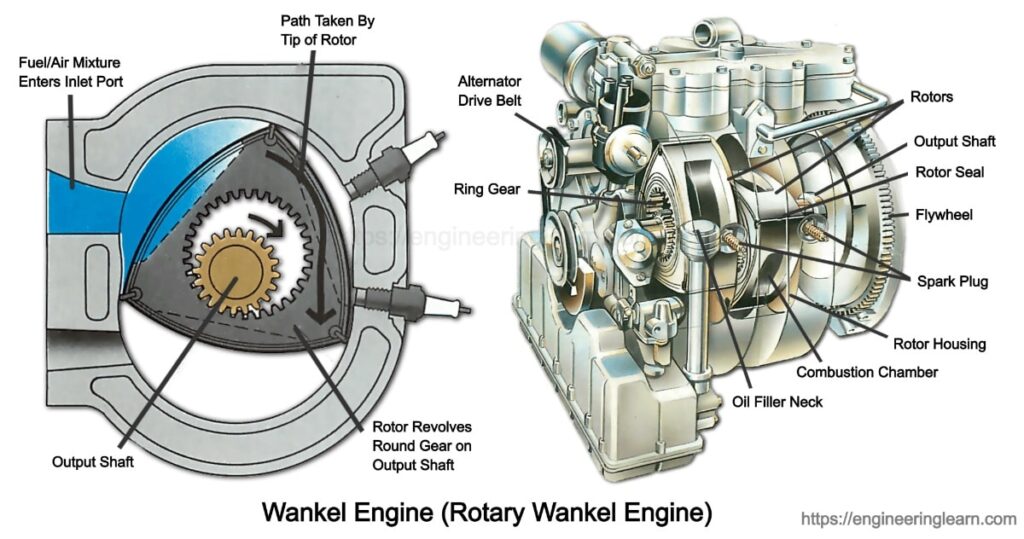
Wankel Engine Working Principle and Applications :- Wankel engine is referred to as that type of internal combustion engine which works only by using an eccentric rotary design in order to convert the pressure into the rotating motion. While comparing it with the reciprocating piston engine, the Wankel engine is found having more uniform torque and less vibration as compared with the other. Also it is found to be more compact and weighs less.
The rotor is responsible for creating the turning motion which is quite similar in shape to a Reuleaux triangle. Wankel engines are the ones which deliver three power pulses per revolution of the rotor by completing the Otto cycle. Whereas, the output shaft uses toothed gears which helps to turn it almost three times fast and gives it one power pulse per revolution. One revolution comprises of a rotor which experiences power pulses and exhausts gas simultaneously, where the four stages of the Otto cycle occur at different time intervals.
For instance, considering a two-stroke piston engine there is only one power pulse for each crankshaft revolution whereas in a four-stroke piston engine, there is one power pulse for every two revolutions. The numerous levels of the Otto cycle involves intake, compression, ignition, and exhaust which occurs at each revolution of the rotor at each of the three rotor faces going inside the oval-like epitrochoid housing in order to enable the three power pulses per rotor revolution.
The principle of displacement is applied to only one face of the rotor as only one face is working for the output of each shaft revolution. The engine is known as a rotary engine, because the name is given to the completely different designs, which include the rotary engines with pistons and without pistons.
Design Of A Wankel Engine
The Wankel engine is designed in a quite compact way which weighs less as compared to any other engine that employ reciprocating pistons. It gives various applications in vehicles and devices, automobiles, motorcycles, racing cars, aircraft, go-karts, jet skis, snowmobiles, chainsaws, and auxiliary power units. Numerous engines are found having the power-to-weight ratio around one horsepower per pound. Mostly all the engines are designed which comprise of a spark ignition, with compression ignition engines which has been built only in the research projects.
Usually in the Wankel engine, the four strokes of an Otto cycle occur in the space within each face of a three-sided symmetric rotor and also inside a house. The bow shaped triangular rotor is covered by an oval shaped epitrochoid which faces similarity in appearance to a Reuleaux triangle.
The theoretical shape of the rotor amongst the fixed apexes results in minimization the volume of the geometric combustion chamber and maximizes the compression ratio respectively. The symmetric curve is used for connecting two arbitrary of the rotor which is maximized in the direction of the inner housing shape with the constraint that it does not touch the housing at any angle of the rotation.
The drive shaft at the center is referred to as an eccentric or E-shaft which passes through the center of the rotor and is found being supported by the fixed bearings. These rotors ride on the eccentrics which provide the integral of the eccentric shaft. Both the rotors rotate around the eccentrics in order to make an orbital revolution around the eccentric shaft. There are seals at the parts of the rotor which seals it against the periphery of the housing and divides it into three moving combustion chambers.
Working Of A Rotor
The rotation of each rotor on its own axis is caused as well as controlled by a pair of gears. The gears are found to be mounted on one side of the rotor which engages a ring gear attached to the rotor and ensures the rotor to move one-third turn for each of the eccentric shaft. The power output of the engine is not transmitted by the synchronizing gears.
The movement of the rotor is in its rotational motion which is guided by the gears and the eccentrically shaft, not being guided by the external chamber. The rotor should not be rubbed against external engine housing. The force of gas pressure on the rotor puts pressure at the center of the eccentric part of the output shaft.
The most accurate way to visualize the action of the engine in the animation is to not at all look at the rotor, where the cavity created between it and the housing. The Wankel engine is also referred to as a variable-volume progressing-cavity system where the three cavities per housing repeat the same cycle consistently. There are two points on the rotor, point A and B and E-shaft which turns at different speeds whereas point B turns three times as compared to point A.
This is designed in order to get one full orbit of the rotor equated to three turns of the E-shaft. As the rotor undergoes orbital revolving, each side of the rotor moves closer to it and then away from the wall of the housing, which compresses and expands the combustion chamber for instance, the strokes of a piston in a reciprocating piston engine. The power vector of the any combustion stage undergoes the center of the offset lobe.
Why One Should Prefer A Four Stroke Engine?
A four-stroke piston engine is the one which completes only one combustion stroke per cylinder for every two rotations of the crankshaft which is referred to as half power stroke per crankshaft rotation per cylinder in the Wankel engine which generates one combustion stroke per driveshaft rotation which means one power stroke per rotor orbital revolution and three power strokes per rotor rotation.
Therefore, the output which is achieved in terms of power from a Wankel engine is usually found higher than that of a four-stroke piston engine which gets displaced in a similar state with more than four-stroke piston engine with similar physical dimensions and weight.
These are usually the engines which reach a quite higher engine revolutions as compared to reciprocating engines of a similar power output. This is done to partly smoothing the inherence in a circular motion, and the fact that the rpm of the engine is from the output shaft, which is three times faster than the speed of the oscillating parts. The eccentric shaft does not have any stress-related contours of the crankshafts. The maximum number of revolution of a rotary engine is limited to an extent by the tooth load on the gears.
Steel gears which are used for extended operation above 7000 or 8000 rpm are mostly quite hard. The applications of a Wankel engine is mostly in an auto racing cars which is operated above 10,000 rpm. Specifically in the case of aircrafts, it is conservatively up till 6500 or 7500 rpm, but as soon as the gas pressure participates in the sealing efficiency, the Wankel engine at high revolutions under goes no-load conditions which can destroy the engine.
How Do National Agencies Consider Wankel Engines?
All the National agencies which tax the automobiles according to the displacement and regulatory bodies considers the Wankel engine equivalent to a four-stroke piston engine of up to twice the displacement of one chamber per rotor, although there are three lobes per rotor as it completes only one-third rotation per one rotation of the output shaft therefore, only one power stroke occurs per working per output revolution and the other two lobes eject a spent charge by taking in a new one, instead of contributing to the power output of that revolution.
There are racing series which were banned by Wankel engine accompanied by all its other alternatives to the traditional reciprocating-piston of a four-stroke design.
Recent Developments In The Engine
The Increased displacement and power of the rotary engine has added more rotors to its basic design but a limit still exists in the number of rotors, as the power output is channeled through the last rotor shaft with all the stresses present at the whole engine present at that particular point. The engines had rotors accompanied by two bi-rotor sets and a serrate coupling amongst the two rotor sets have been tested successfully.
The recent research in the United Kingdom under the Self-Pressurizing-Air Rotor Cooling System (SPARCS) project, found that an idle stability and economy was obtained by supplying an ignitable mix to only one rotor in a multi-rotor engine which is a forced-air cooled rotor quite similar to the Norton air-cooled design.
The main drawback of a wankel engine are as follows:
• Inadequate lubrication
• Cooling in ambient temperatures
• Short engine lifespan
• High emissions
• Low fuel efficiencies
Material Used In Wankel Engine
Unlike a piston engine which includes the cylinder that is heated by the process of combustion which then is cooled by the incoming charge. The housings of the Wankel rotor kept on heating consistently from one side and is cooled on the other which leads to high local temperatures and unequal thermal expansion. The place is high in demand on the type of material used whereas the simplicity of the Wankel engine makes it quite easier to use as an alternative material like the alloys and ceramics.
While water cooling in a radial or axial flow direction and hot water from the hot bow heating the cold bow, the thermal expansion remains un disturbed. Considering the temperature of a top engine can be decreased up to 129 °C with a maximum temperature difference of 18 °C between the parts of the engine by the use of heat pipes all around the housing and in the side plates as a cooling means.
The alloys which are cited for Wankel housing use are A-132, Inconel 625 and 356 which is treated to T6 hardness. There are various materials which have been used for plating the housing working surface, one amongst which is Nikasil. For instance, Mercedes-Benz, Ford, etc. are applied for patents in this field.
The perfect combination within a housing plating, apex and materials of side seals is determined with the help of experiments in order to obtain the best duration of both the seals and housing cover. Specifically for the shafts, material preferred is steel alloys with little deformation on load. Also the use of Maraging steel is proposed for this purpose.
Lubrications Of Wankel Engine
The leading fuel gasoline was a predominant type which was available in the first years of the development of Wankel engine. Lead refers to as a solid lubricant which is known as the leading gasoline and is designed to decrease the wearing of seal and housings. The engines of the ancient era had the calculated oil supply with consideration of gasoline’s lubricating qualities.
Once the gasoline is removed, the engine develops a need of an increased mix of oil in the gasoline in order to provide lubrication to the critical engine parts. Experienced people advise that the engines with electronic fuel injection should add at least 1% of oil directly into the gasoline as a safety measure in case the pump which is responsible for providing oil to combustion chamber or the related parts failed or sucked in air.
There were various approaches which involved solid lubricants and even added MoS2 at the rate of 1 cc per liter of fuel. Many engineers have agreed to it that the addition of oil to gasoline in old two-stroke engines was a safer approach for the reliability of the engine as compared to an oil pump being injected into the intake system or directly to the part which required lubrication.
Sealing Problems In Wankel Engine
The engines of the ancient era were designed in such a way that they had a high incidence of sealing loss between the rotor and the housing and sometimes also between various pieces which made up the housing. These were the Mazda engines which required to be rebuilt after every 50,000 miles or 80,000 kms. Other than this the sealing problems persisted from the uneven thermal distribution within the housings which caused distortion and loss of sealing and compression.
The problem persisted when the engine was stressed before reaching its operating temperature. Whereas, Mazda rotary engines were successful in solving these initial problems. This problem of clearance for hot rotor apexes passed between the axially closer side housings in the cooler intake lobe areas which dealt using an axial rotor pilot radially inboard of the oils seals including the improved inertia oil which cooled the interior of the rotor.
Fuel Economy And Its Emissions
The Wankel engine has certain problems in its fuel efficiency and emissions while burning gasoline. The Gasoline mixtures are quite slow to ignite and also have a slow flame propagation speed with a higher quenching distance on the compression cycle of 2 mm as compared to that of a hydrogen being 0.6 mm. Combining these factors waste fuel had created power which reduced its efficiency.
The gap present between the rotor and the engine housing is too narrow for gasoline on the compression cycle whereas is quite wide for hydrogen. The narrow gap is kept to create compression. Once the engine uses gasoline, the remaining gasoline is ejected into the atmosphere through the exhaust. This is not a constraint while using a hydrogen fuel, as all the fuel mixture in the combustion chamber is burnt which nearly gives no emission and increases the efficiency of fuel by 23%.
Shape Of The Wankel Combustion Chamber
The shape of the Wankel combustion chamber is designed in such a way in order to make it more resistant to pre ignition operation on the lower-octane which rates the gasoline as compared to the piston engine. The shape of the combustion chamber may also lead to incomplete combustion of the air-fuel charge while using gasoline fuel. This can result in releasing a larger amount of unburned hydrocarbons from the exhaust.
Whereas, the exhaust is relatively low in emissions as the combustion temperatures are mostly less as compared to those in other engines and also because of exhaust gas recirculation (EGR) in the early engines. In the early 1920 it was known that there was an increase of 1% in the proportion of exhaust gas in the admission mix, which created a 7 °C reduction in the flame temperature. This helps in allowing the Mazda to meet the laws of United States Clean Air Act of 1970 in the year 1973, in a simple and inexpensive manner, which was an enlarged chamber in the exhaust manifold.
By reducing the air is to fuel ratio, the unburned hydrocarbons in the exhaust supported the combustion process in the thermal reactor. Cars with piston-engine require expensive a catalytic converter to deal with both the unburned hydrocarbons and their emissions.
The solution for increasing the fuel consumption was not economical. Whereas the sales of the rotary engine cars suffered due to the oil crisis of 1973 which raised the price of gasoline which decreased the sales. The injection of air into the exhaust port zone which improved the fuel economy and reduced emissions was discovered by Toyota.
SPARCS And Compact-SPARCS
SPARCS, Compact-SPARCS, CREEV (Compound Rotary Engine for Electric Vehicles) are the ones which provide heat rejection and are efficient in thermal balancing which optimizes the lubrication. The constraint which existed with a rotary engines was that the engine housing has a permanently cool and hot surface while working.
This generates excessive heat inside the engine which breaks down the lubricating oil quickly. The SPARCS system decreases the wide differential in the heat temperatures of the engine housing which also cools the rotor from inside body of the engine.
This results in a decreased engine wear which prolongs the life of the engine. The self-pressure is captured by blowing the rotor side gas which seals from the working chambers. CREEV refers to as an exhaust reactor which contains a shaft & rotor inside having a different shape to the rotor of the Wankel engine.
The reactor which is located inside the exhaust stream consumes the un burnt exhaust products without using the second ignition system before sending the burnt gasses into the exhaust pipe. Horse power is given to the reactor shaft which helps in achieving lower emissions and improved fuel efficiency is achieved. Whereas, all the three patents are currently licensed to the engineers of UK.
Catalytic Converting Systems In Wankel Engine
Mazda is responsible for shifting the catalytic converter system with reference to the research factor that controls the amount of unburned hydrocarbon which is in the exhaust making the rotor surface temperature, with higher temperature producing quite less hydrocarbon.
The rotor can also be widened which keeps the rest of engine unchanged which reduces the friction and increases the displacement and power output. The limiting factor for widening was mechanical especially when the deflection of shaft was seen at higher rotative speeds. Quenching is the most dominant source of hydrocarbon at comparatively high speed and leakage at low speed.
The automobiles with Wankel rotary engines are capable of high-speed operations. Whereas, it was shown that the early opening of an intake port, long intake ducts and great rotor eccentricity was found increasing the torque at a lower rpm. The shape and position of the recess in a rotor forms most of the combustion chamber which influences the rate of emission and fuel economy.
This results in terms of fuel economy and exhaust emissions which is variable and depends upon the shape of the combustion recess and is determined by the placement of the spark plugs per chamber of an individual engine.
Low Emitting Vehicles
The car which has Renesis engine can meet the requirements of the California State fuel economy which includes the low emission vehicle standards (LEV). This was achieved by various innovations. Whereinthe Mazda rotaries were also located in the rotor housings. This was helpful in solving the problem of the earlier ash which was formed in the engine and the thermal distortion of the side intake and the exhaust ports. A scraper seal was also added in the sides of the rotor including some ceramic parts which were used in the engine. This helped Mazda in eliminating the overlap between the intake and the exhaust port opening while continuously increasing the exhaust port area.
The side port gets trapped in the chamber of an unburned fuel which decreases the consumption of oil and also improves the stability of combustion in a lower speed and light load range. The HC emissions from the side exhaust port of a Wankel engine are 35–50% reduced as compared to those which are from the peripheral exhaust port of the Wankel engine due to zero intake and exhaust port opening. The peripheral ported rotary engines had a comparatively better pressure which especially at high rpm and a rectangular shaped intake port.
Next generation Wankel Engines
Mazda is still developing the next-generation Wankel engines. The company is intending to make laser ignition engines which will eliminate the conventional spark plugs and will work on direct fuel injection or sparkless HCCI ignition and SPCCI ignition. This leads to a greater rotor eccentricity with an improved elasticity and lower revolutions torque with respect to time.
The studies proved that the installations of a combustion chamber improved the partial load and decreased the revolutions per minute with fuel economy of 7%. The motive was to improve the fuel efficiency for which Mazda is looking to use the Wankel as a range-extender in its series of hybrid cars and announcing a prototype. This configuration helps in improving the fuel efficiency and the emission rate. As an advantage, running a Wankel engine at a consistent speed will give you a greater engine life.
In the year 2015 there came a new system to which reduced the emissions and increased the efficiency of the fuel with the Wankel Engines which was developed by the UK-based engineers following a licensing agreement in order to utilize the patents from the Norton rotary engine creator.
The Compound Rotary Engine for Electric Vehicles (CREEV) system uses a secondary rotor in order to extract the energy from the exhaust which consumes the unburnt exhaust products while the expansion occurs in the secondary rotor stage in order to reduce the overall emissions and fuel costs by recouping the exhaust energy which would otherwise have been lost. To expand the exhaust gas near atmospheric pressure, Garside ensured that the engine exhaust should remain cooler and should produce less noise.
Laser Ignition In Engines
Earlier the spark plugs needed to be indented into the walls of the combustion chamber which allowed the apex of the rotor to get enabled and to sweep past. As the apex of the rotor gets seals pass, around the hole of the spark plug, a very small amount of compressed charge gets lost from the charging chamber of the exhaust chamber which entails fuel in the exhaust and thus reduces its efficiency which results in higher emissions.
These are the points which have overcome using the laser ignition and thus eliminating the earlier spark plugs and also removing the narrow slit in the motor housing so that the rotor apex seals can be fully swept with no loss of compression from the adjacent chambers. The laser plug can fire using the narrow slit which helps in firing deep into the combustion chamber with the help of a multiple laser. So the higher compression ratio is preferred. The direct fuel injection into the Wankel engine is suited and is combined with the help of laser ignition in single or multiple laser plugs which has been shown in order to enhance the motor by reducing the disadvantages.
Homogeneous Charge Compression Ignition (HCCI)
Homogeneous charge compression ignition (HCCI) includes the usage of pre-mixed air-fuel mixture which is compressed to the point of an auto-ignition therefore the electronic spark ignition gets eliminated. The gasoline engines are those which combine with the homogeneous charge (HC) spark ignition (SI which is also known as HCSI. The diesel engines are combined with stratified charge (SC) and compression ignition (CI) which is together known as SCCI. The HCCI engines achieves the gasoline engine-like emissions with the help of a compression ignition engine-like efficiency, and the lower levels of nitrogen oxide emissions without using any catalytic converter.
Mazda has done various studies on the HCCI ignition for the latest rotary engine project with the help of research from its SkyActiv Generation 2 program. The foremost constraint of a rotary engine is that it needs to be shifted outside the spark plug of the combustion chamber in order to enable the rotor to sweep past.
Spark Controlled Compression Ignition (SPCCI)
Mazda has under gone a successful research on Spark Plug Controlled Compression Ignition (SPCCI) ignition on rotary engines which states that a newly introduced rotary engines will incorporate SPCCI. SPCCI inculcates spark and compression ignition which combines the advantages of a gasoline and diesel engines in order to achieve the environmental, power, acceleration and the goals of the fuel consumption.
A spark will always be required in the combustion process which will depend upon the load which it might be during the spark ignition. Therefore, a spark is required to control whenever the combustion occurs. The aspect of compression ignition of SPCCI helps it in making possible a super leaning burn which improves the efficiency of the engine up to 20–30%. SPCCI gives a very high efficiency across the widest range of rpms and engine loads.
The mode of engine is lean-burn which is about 80% of the running time. The spark plugs ignites a small pulse of the lean mixture which is injected into the combustion chamber. Whenever fired a fireball is made which acts like an air piston which increases the pressure and temperature in the combustion chamber. The compression ignition of a lean mixture occurs with a rapid and even burn which leads to a more powerful cycle. The time of combustion is controlled by the flame from the spark plug which enables SPCCI to get the advantages of both petrol and diesel engines.