Types of governors
Types of governors
Introduction
Governor is a device which is used to maintain the speed of an engine within specified limits, whenever there is a variation of load. In general, the speed of an engine varies in two ways- cyclic variation, i.e. variation during each revolution, and variation over a number of revolutions. In cyclic variations, the variations in the speed are due to variation in the output torque of the engine during a cycle and can be regulated by mounting a suitable flywheel on the shaft. The variations in the engine speed over a number of revolutions (the latter case) are caused due to variation in the load on engine and in order to maintain speed, a governor is used in this case.
A governor is essential for all types of engines as it adjusts the supply as per demand, even in the cases when flywheel is not usable.
Types of governors
Broadly speaking, governors are divided into two categories, and this classification is based on how they operate, i.e. which force balances the controlling force.
Controlling force is defined as the inward force on the balls of the governor when it is running at a steady speed.
The two categories of the governors are:
- Centrifugal governor
- Inertia governor
Detailed description of the two categories is given below.
1. Centrifugal governors:
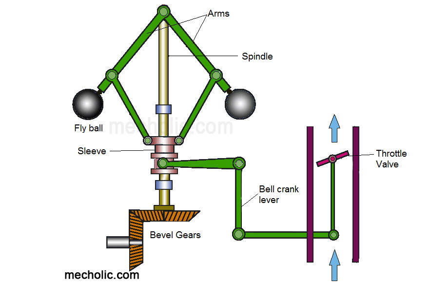
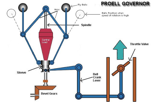
This is the most commonly used type of the governors. Its action depends upon the variation in speed. It consists of a pair of masses called governor balls, rotating with a spindle. In these governors, the inward directed controlling force is balanced by the centrifugal force produced by the masses of two balls. Increase in engine speed, causes the balls governor balls to rotate at a greater speed, and thus at a greater radius from the axis. This in turn causes the upward slip of the sleeve which is controlling a throttle valve via a bell crank lever. The upward movement of sleeve causes a closure of throttle valve to the required extent. Thus the supply of fuel to the engine decreases and the desired speed is maintained.
Figure 1 gives the visual overview of a centrifugal governor.
2. Inertia governor:
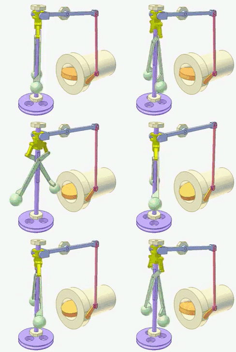
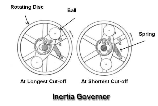
In this type of governor, in addition to the the centrifugal force generated by the revolution of the governor balls around the axis, there is an additional inertia force which is generated by the angular acceleration or deceleration of the spindle. This inertia force is generated because the governor is connected to the flywheel or the crankshaft of the engine, as shown in the figure 2. Thus the balls are operated by the rate of change of engine speed as compared to the centrifugal governors in which balls are operated by actual change of engine speed. Therefore the response of inertia governor is faster than that of centrifugal governors.
Comparison between the two types:
- The operation of centrifugal governor depends upon the change in the engine speed and the centrifugal force on the governor balls while in the inertia governor the operation is dependent upon the acceleration and deceleration of the engine.
- Only centrifugal force operates against the controlling force in centrifugal governor, while in inertia governor, inertia force along with the centrifugal force acts against the controlling force.
- Centrifugal governor is less sensitive as compared to the inertia governor.
- In centrifugal governor, it is easier to balance the revolving parts as compared to the inertia governor.
- Centrifugal governors are more popular as compared to inertia governors.
Here are some detailed examples of the different types of centrifugal governors:
A) Watt governor:
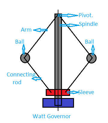
It is simplest and the gravity controlled type of centrifugal governor. In this governor, there are two fly balls attached to the sleeve which has a negligible mass. In some places it is also defined as a pendulum type centrifugal governor. Upper end of the arms attached to the balls is pivoted, enabling the balls to move up and down during the revolution. Lower ends of the lower arms are connected to the sleeve, which too rotates along with the spindle. At the same time it can slide up and down along the spindle too. Spindle is driven by the engine via bevel gears. The speed of the engine increases with decrease in load on it. This increase causes an increase in the revolution speed of the spindle, thus the governor balls tend to move outward and the sleeve moves upward. This in turn closes the throttle valve linked to the sleeve via bell crank lever and the fuel supply to the engine decreases and thus its speed decreases too.
B) Porter governor:
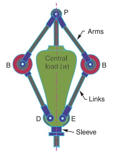
It is a gravity controlled centrifugal governor. The construction of porter governor is same as watt governor, but with a slight modification. In this governor, the sleeve is also loaded with a heavy mass. The working mechanism of this governor is same as that of watt governor.
C) Proell governor:
It can be broadly described as a porter governor which a slight difference in the way the governor balls are attached. Unlike the porter governor, in which the balls are directly attached to upper and lower arms, in Proell governor, they are attached to an upward extension arm each. (Figure 5)
D) Hartnell governor:
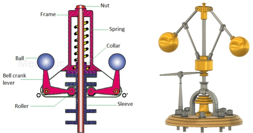
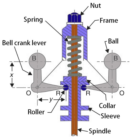
This is a spring controlled centrifugal governor. In this governor, a spring fitted along the spindle controls the movement of the governor balls and thus the sleeves. The spring is initially fitted in compression, so that a force is exerted on the sleeve. It consists of two bell crank levers. Each one carries a mass at one end and a roller at the other end. Both are pivoted to a pair of arms which rotate along with the spindle. The rollers are fitted into a groove in the sleeve. Increase in engine speed causes the balls to move away from the spindle axis and the sleeve moves upward. The spring force can be adjusted with the help of a screw cap or a nut. (Figure 6)
E) Hartung governor:
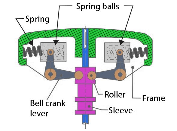
It is another kind of spring controlled centrifugal governor. But in this governor, the spring forces aren’t used along the spindle axis. Instead spring forces are used through spring balls which have springs compressing against the frame of the governor. These spring balls are fitted with the vertical arm of the bell crank levers. The horizontal arms of the bell crank lever are attached to the rollers which fit into the grooves of the sleeve and press against it. The spring force of the spring ball resists the centrifugal force acting on the spring ball. (Figure 7)
Application of governors :
- RPM control of aircraft propellers.
- RPM control of small engines used to power lawn mowers, garden tractors, generators, etc. In these applications electronic and pneumatics governors are also used.
- Speed control of steam and water turbines.
- In elevators, governors are used as stopping mechanism if the elevator runs beyond its tripping speed.
